Auto Duct Layout
Visual duct designer on the ducted floor plan wizard. Auto-route or draw by hand. Includes outdoor unit and refrigerant pipework. Drives the take-off.
Auto Duct Layout
Design your ducts on the floor plan in one click, or draw by hand. Now with multi-level support.
- Auto Layout routes plenums, BTOs, DBTOs, flex runs, dampers, outlets, outdoor unit and refrigerant pipework
- Two-storey homes are first-class: choose single system with droppers or dual system, one per level
- Manual droppers connect levels and the matching outlet appears on the floor below automatically
- Toggle the Overlay view to stack both levels on the same canvas and check risers line up
- Full parts library with real-world sizing driven by your floor plan scale
- Drawn layout flows into the take-off automatically, so the order matches reality
- Works on desktop and touch: pointer events throughout
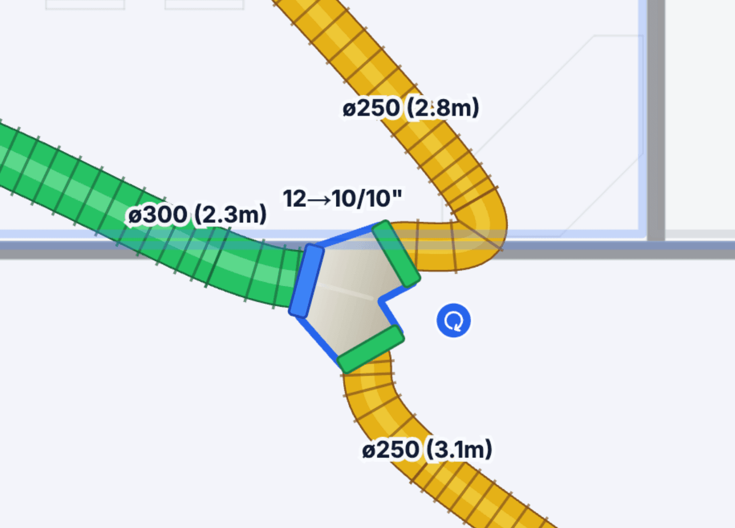
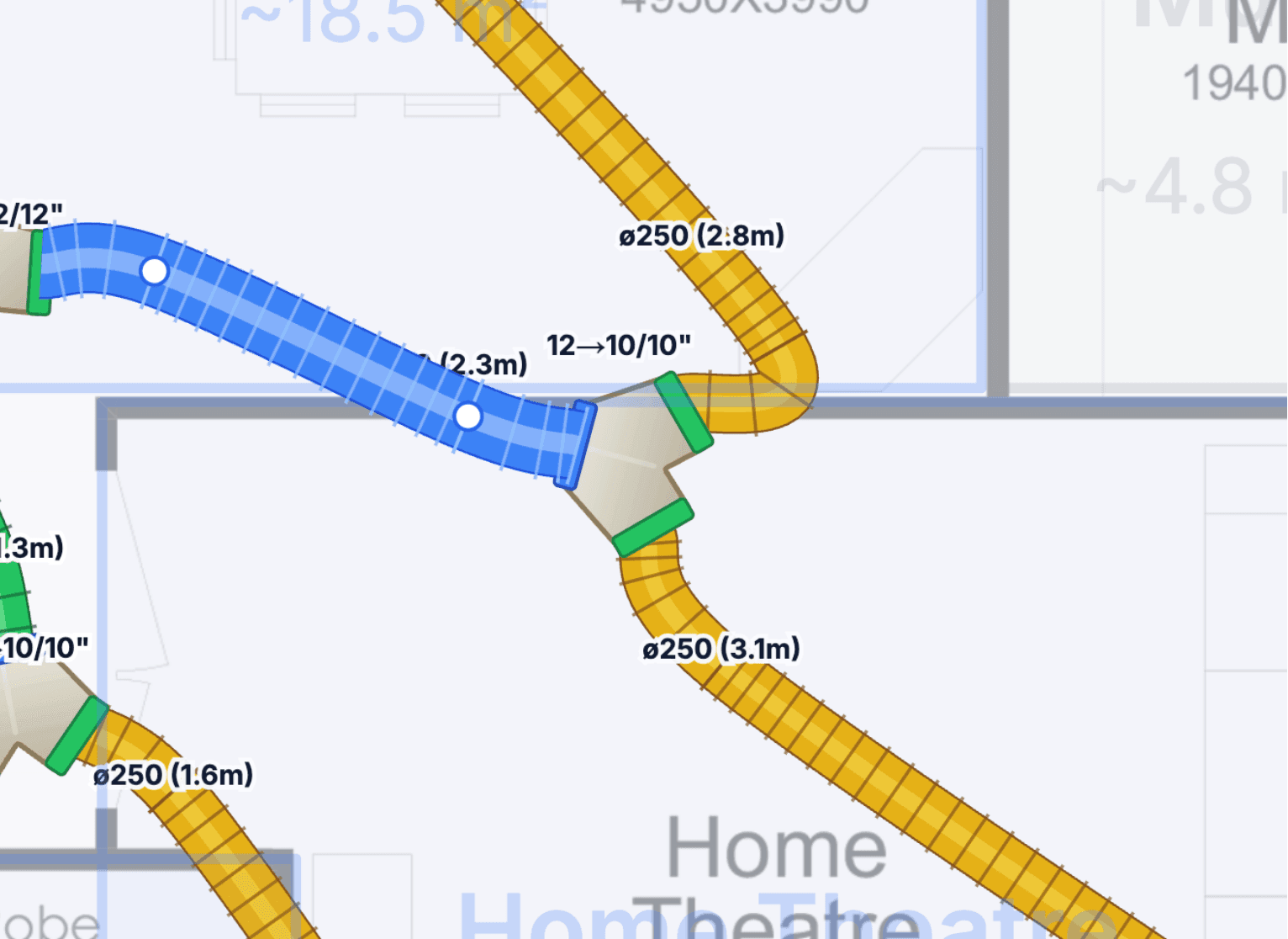
- Labels on the plan show real duct sizes and lengths (e.g.
ø250 (2.8m)) and reducer ratios on fittings (e.g.12→10/10")
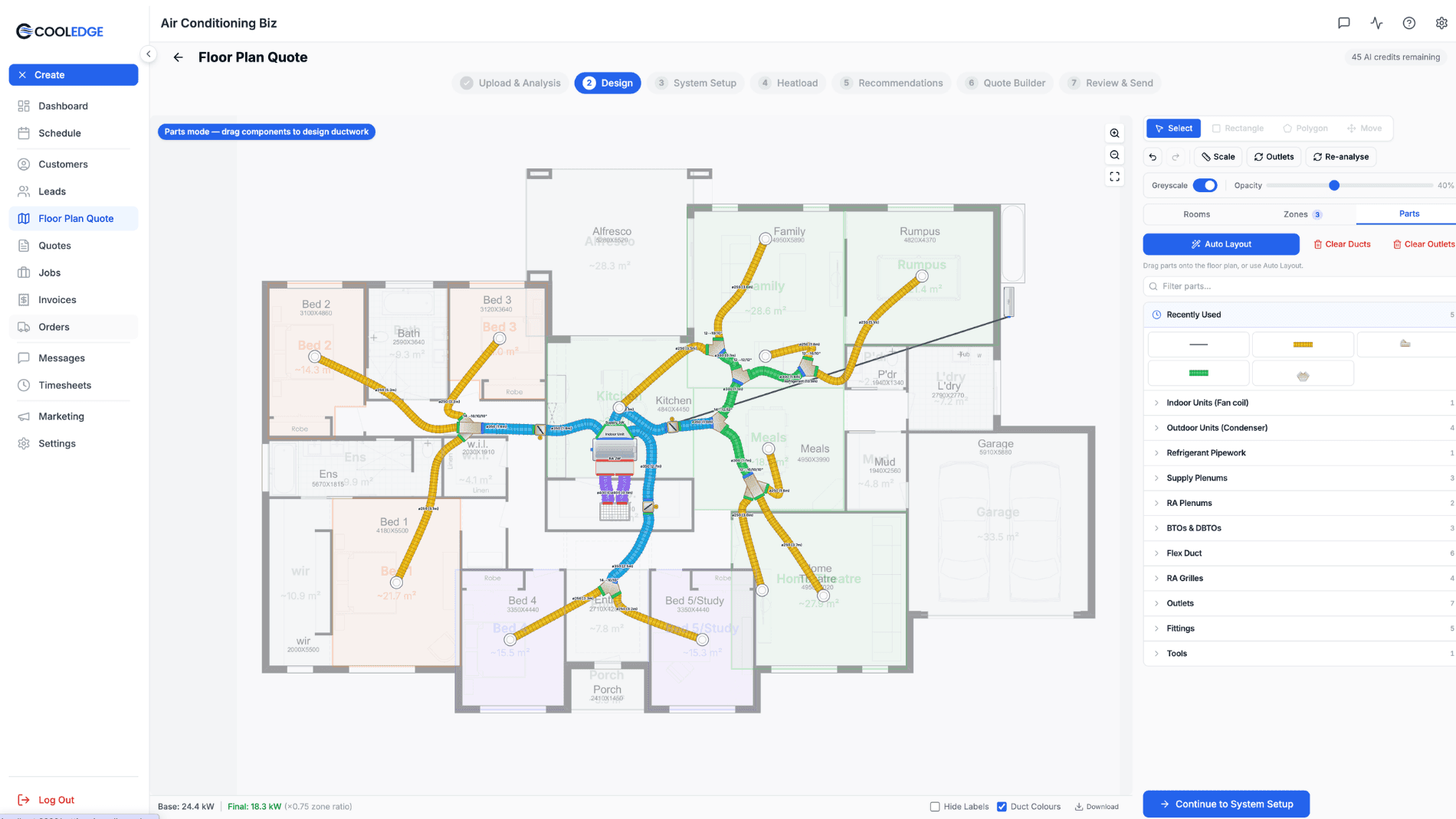
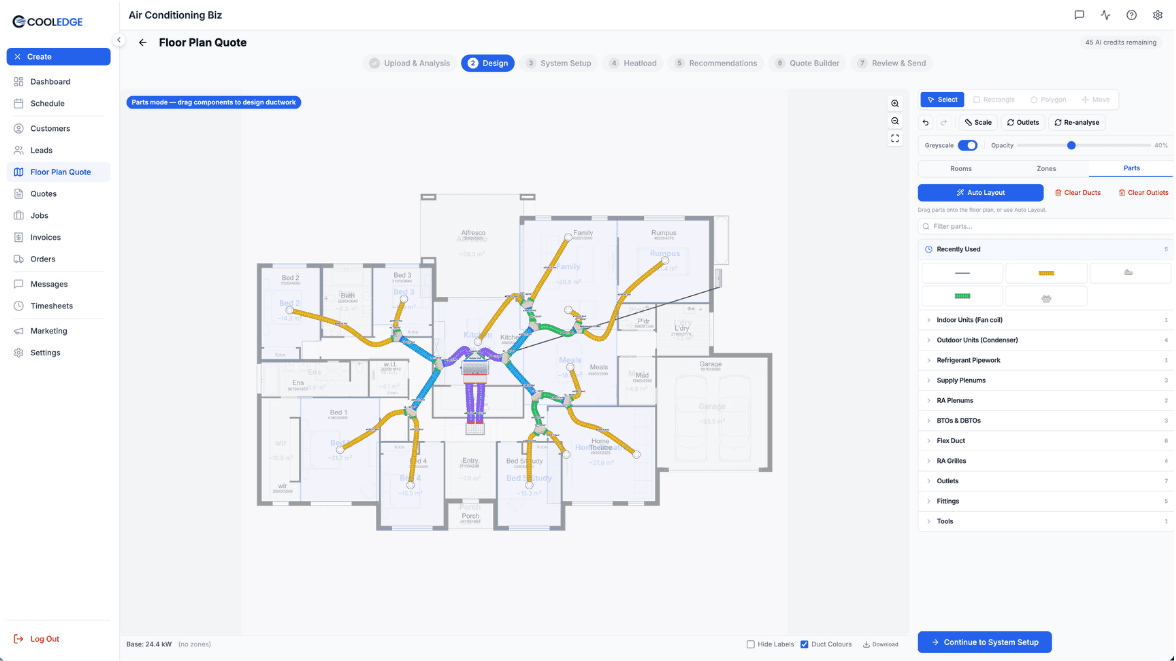
Auto Duct Layout is a visual duct designer built into the ducted floor plan wizard. It adds a Parts tab alongside Rooms and Zones on step 1, where you can auto-route an entire duct system in one click or draw it by hand. The drawn layout drives your take-off automatically, so what you see on the plan is exactly what ends up on the quote and the supplier order.
What You Need
- An active Cooledge subscription
- A completed ducted floor plan (rooms reviewed, scale set, zones assigned)
- Your ducted catalogue configured (plenums, BTOs, DBTOs, flex, dampers, outdoor units, refrigerant pipework)
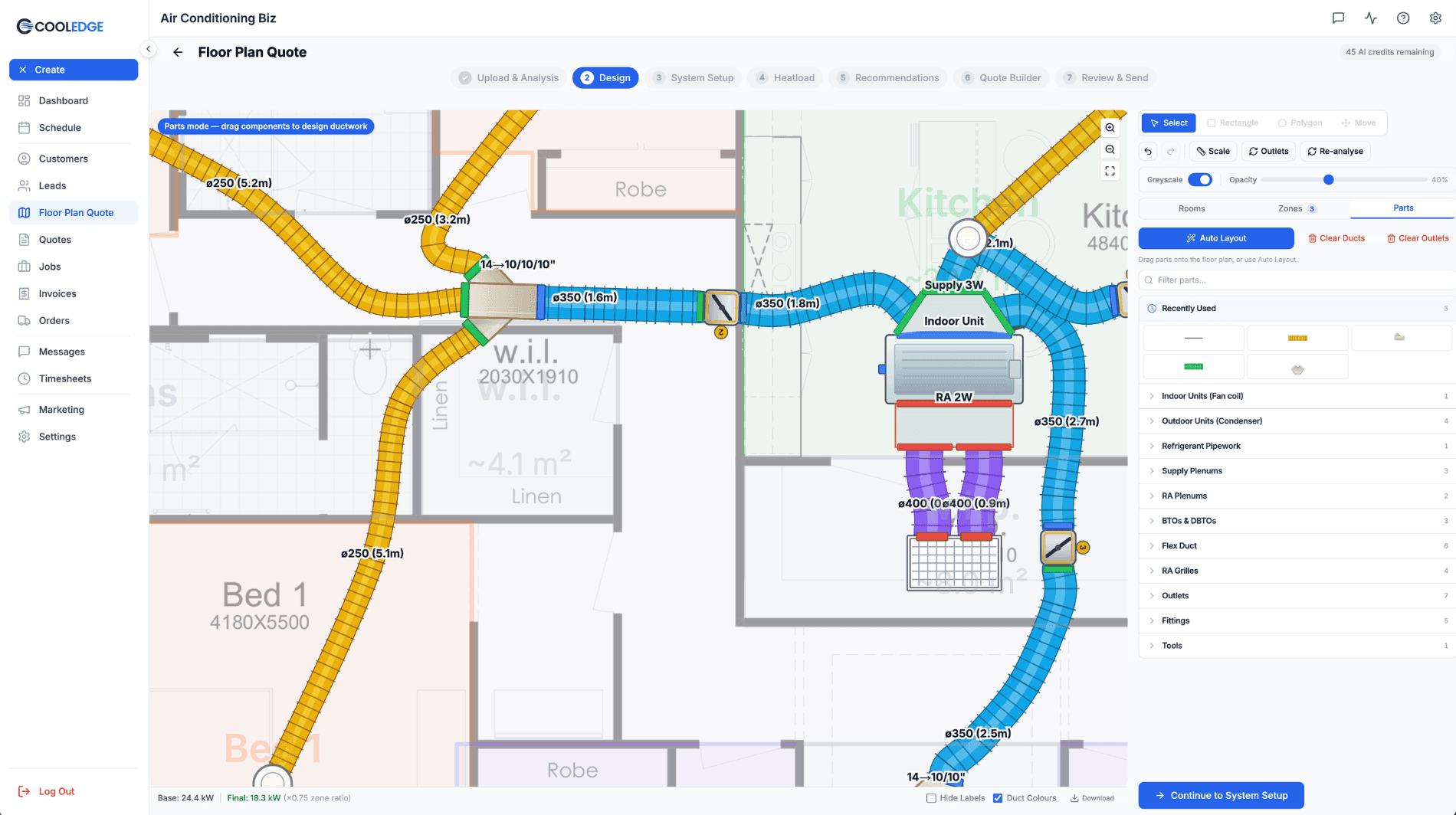
The Parts Tab
On step 1 of the ducted floor plan wizard you'll see three tabs at the top of the right sidebar: Rooms, Zones ([count]) and Parts.
Switching to Parts transforms the floor plan into an interactive design canvas. The same plan you scanned and zoned is now the backdrop for laying out the duct system.
Top Toolbar
The top toolbar switches to drawing mode when Parts is active:
- Drawing tools — Select, Rectangle, Polygon, Move
- Actions — Undo, Redo, Scale, Outlets, Re-analyse
- View controls — Greyscale toggle, Opacity slider (default 40%)
The Greyscale toggle and Opacity slider both affect the underlying floor plan image, so you can dim the background and focus on the duct layout while drawing. The Outlets action jumps straight to outlet management without reopening Auto Layout. Re-analyse re-runs the AI room detection on the original image if you want fresh polygons.
Parts Panel Header
At the top of the Parts panel on the right sidebar:
- Auto Layout — the primary blue button that generates the full system
- Clear Ducts — removes all drawn ducts, plenums and fittings (red text)
- Clear Outlets — removes placed outlets (red text)
- Filter parts... — search box for the parts library
Auto Layout
The fastest way to design a system. One button, one modal, one fully routed layout.
- Make sure your zones are set on the Zones tab and the heatload is finalised
- Click the Auto Layout button at the top of the Parts panel
- Confirm in the modal (this replaces any existing drawn layout, but pinned outlet positions are preserved if you opt in)
- Cooledge places:
- An indoor unit (fan coil) near the return-air position
- A plenum sized to the system — 1-Way, 2-Way or 3-Way Supply Plenum based on zones
- BTO and DBTO fittings for zone splits, inserting reducer fittings as the duct size steps down
- Flex runs to each outlet, coloured by size (150, 200, 250, 300, 350, 400 mm)
- Dampers on the branch serving each zone
- Outlets in each conditionable room, using your default outlet type
- An outdoor unit (condenser) with refrigerant pipework back to the indoor unit
Auto Layout mirrors the same algorithm Cooledge uses for the take-off, so the drawn layout and the take-off stay in sync by construction.
Tip: Set your zones on the Zones tab before hitting Auto Layout. Zones drive the plenum shape (1-way / 2-way / 3-way) and damper placement. Without zones, the auto layout produces a single-motor system with no zoning.
Important: Auto Layout replaces the current drawn layout by default. If you've already hand-tweaked the drawing and want to keep pinned outlet positions, confirm the "preserve pinned outlets" option in the modal before regenerating.
Multi-Level Designs
If your floor plan has Ground and Level One (or beyond), each level shows as its own tab at the top of the Parts panel. You design each level independently and the take-off rolls them all into one supplier order.
Choose Your System Mode
When you hit Auto Layout on a multi-level plan, you'll pick one of two modes:
- Single system with droppers — one indoor unit (usually in the ceiling space above Level One) feeds both levels. Cooledge places droppers down through the ceiling to serve Ground-floor outlets. The riser depth is set by the floor-to-floor height in Settings → Floor Plan → Ducted AC Defaults.
- Dual system, one per level — separate indoor and outdoor units for each level. Each level gets its own zoning, its own plenum and its own outdoor unit. Common for larger homes or where the upper-floor ceiling space is limited.
Manual Droppers
You can also place droppers by hand in single-system mode:
- Switch to the Level you want the dropper to feed from (usually Level One)
- Pick the Dropper part from the Parts panel
- Click to place it at the ceiling penetration point
- The dropper's matching outlet automatically appears on the level below at the same coordinates
- Connect a flex run from a BTO/DBTO to the dropper and another flex run from the floor-below outlet to the destination diffuser
The riser height (floor-to-floor distance) is automatically derived per-dropper and included in the take-off, so longer droppers in homes with high ceilings carry the right riser length.
Overlay View Between Levels
Toggle the Overlay view on the Floor Plan Scanning step to see Ground and Level One stacked on the same canvas. It's the fastest way to check that risers, droppers and stacked rooms line up across levels. If the footprints don't match perfectly, use the alignment handle to nudge a level into place.
Tip: Use Single system with droppers for most two-storey homes — it's the cheapest install and the cleanest design. Reach for Dual system, one per level when the upper-floor ceiling space is too tight for full ductwork, or when the two floors have very different conditioning requirements.
Manual Drawing
Use the Parts panel and the drawing tools to place components by hand.
Available Parts
The Parts panel is organised into collapsible categories. Each category shows the actual part tiles you can pick up and place on the plan.
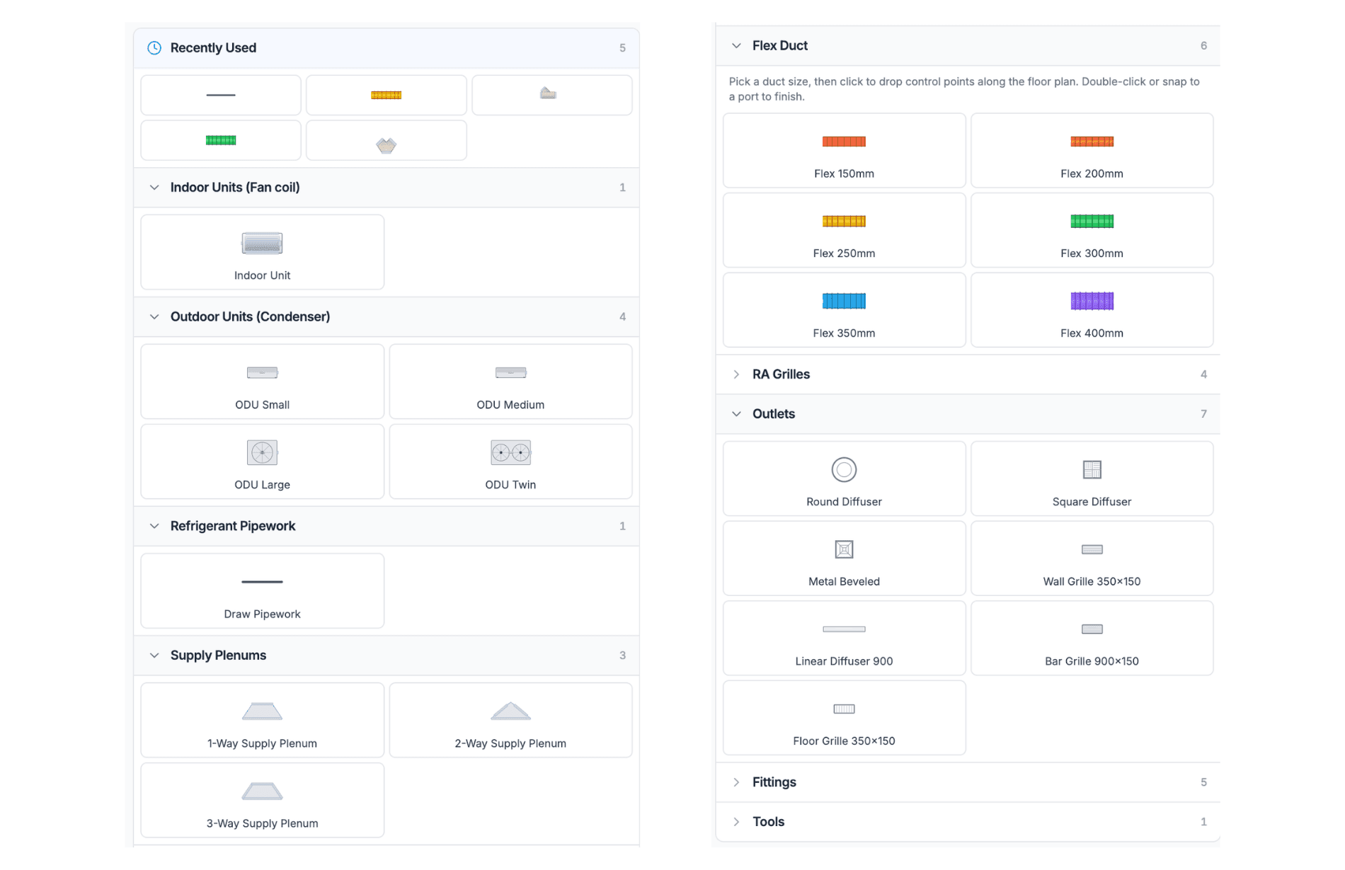
- Recently Used — the parts you placed most recently, for quick reuse
- Indoor Units (Fan coil) — Indoor Unit (rectangular with supply and return-air ports)
- Outdoor Units (Condenser) — ODU Small, ODU Medium, ODU Large, ODU Twin
- Refrigerant Pipework — a Draw Pipework drawing tool (not a drag-drop part) that lets you route refrigerant from the outdoor unit to the indoor unit
- Supply Plenums — 1-Way Supply Plenum, 2-Way Supply Plenum, 3-Way Supply Plenum (shape matches the number of branches)
- RA Plenums — return-air plenum variants
- BTOs & DBTOs — Branch Takeoffs (inverted triangle, 2-way split) and Double Branch Takeoffs (trapezoid, 3-way split), with reducer labels like
12→10/10"showing the inlet and outlet sizes in inches - Flex Duct — six sizes: Flex 150mm, Flex 200mm, Flex 250mm, Flex 300mm, Flex 350mm, Flex 400mm (each with its own colour so a layout reads at a glance)
- RA Grilles — return-air grille variants
- Outlets — seven types: Round Diffuser, Square Diffuser, Metal Beveled, Wall Grille 350×150, Linear Diffuser 900, Bar Grille 900×150, Floor Grille 350×150
- Fittings — miscellaneous fittings (reducers, elbows, end caps)
- Tools — utility tools (measurement, annotations)
Drawing Controls
- Click a part tile in the Parts panel to pick it up
- Click on the canvas to drop the part at that location
- For flex duct: click to drop control points along the path you want the duct to follow, then double-click — or snap to a port — to finish the run
- Drag a placed part to move it — any connected flex ducts follow the fitting automatically
- Double-click a label to rename it
- Ports auto-snap when a flex duct endpoint approaches a compatible fitting port (inlet to outlet, matching size)
- Right-click a control point on a flex duct to remove it (auto-generated points can be re-added by reconnecting the endpoints)
- Use the rotate handle on a selected fitting to rotate it to match the building's angle — great for plans that aren't rectilinear to the page
Tip: Use rotate handles to align fittings to the building's walls, not to the page. A rectilinear plan with 12° walls looks much cleaner when the fittings are rotated to match, and the flex runs stay shorter.
Flex Duct Sizes
Flex ducts come in six standard mm sizes. Each size has its own colour so you can scan a layout for size balance at a glance:
- 150 mm
- 200 mm
- 250 mm
- 300 mm
- 350 mm
- 400 mm
Labels on the floor plan show both diameter and length, for example ø250 (2.8m). BTO and DBTO fittings show their reducer ratio in inches, for example 12→10/10" meaning a 12" inlet splitting to two 10" outlets.
Outlet Management
Outlets can be dragged directly on the floor plan with the Select tool. Pin them where you want them, and the connected flex duct re-routes automatically.
- Pins the outlet at the position you drop it (so re-running Auto Layout won't shove it back)
- Re-routes the flex duct serving that outlet if you move it
- Warns if an outlet ends up outside a conditionable room or inside a no-go zone
Note: Outlet positions pin when you finish dragging. Re-running Auto Layout will preserve pinned outlet positions if you confirm in the modal — otherwise they regenerate from scratch.
Zones and Dampers
Dampers sit on the branch serving each zone, not at each individual outlet. The system:
- Shows each zone with a distinct colour on the plan
- Shows the damper as a yellow-ringed motor icon on the zone branch
- Validates that every conditionable room has a valid path from the indoor unit through a damper
If a room cannot be reached from the indoor unit (for example, because the flex run ends mid-air or is disconnected from the plenum), the Parts panel shows a validation error with a jump-to-the-room button so you can fix it.
The Take-off
The drawn layout flows straight into the take-off. Nothing is added or dropped when the take-off is built:
- Every fitting (BTO, DBTO, plenum, damper, outlet) appears in the take-off
- Flex runs are ordered in whole 6m lengths, with optional joiners for runs over 6m (turn that on in Ducted AC settings)
- The outdoor unit and refrigerant pipework are included alongside the indoor equipment
- Multi-level rollup — every level's parts are summed into one supplier order. Each dropper carries its own riser length into the take-off, derived from your floor-to-floor setting
- Parts not drawn do not appear — the take-off reflects what's on the plan, not a spec-sheet estimate
This means hand-edits (a longer flex run, a different outlet type, an extra damper for a split-zone) all flow through to the quote and the supplier order without a second data entry step.
Want to know how the numbers are worked out? See How Ducted Take-offs Are Calculated for the sizing rules behind the trunk, plenum, branches, flex lengths and joiners.
Settings: Duct Drawing Defaults
Configure default drawing behaviour in Settings → Floor Plan → Ducted AC Defaults tab. Defaults pre-fill on every new floor plan so you only set them once:
- Default flex duct colouring — colour by size or single colour
- Default outlet shape — round / square / linear diffuser
- Default view mode — drawing vs. print
- Whether to show labels on a permanent top layer, or hide them in print mode
Status Bar and Download
At the bottom of the Parts tab you'll see:
- Base: [X] kW — the raw heatload before applying the zoning diversity factor
- Final: [X] kW (×0.75 zone ratio) — the heatload after the zoning diversity factor (0.75 is the default, configurable in Floor Plan settings)
- Hide Labels — toggle every size/length/reducer label on the floor plan
- Duct Colours — toggle colour-by-size vs. a single colour for all flex runs
- Download — export the floor plan plus drawn layout as an image (useful for attaching to the quote PDF or sending to the installer on the day)
Tips
- Trust Auto Layout first. Run it, then tweak by hand. Manual-only is worth it for tight or unusual buildings, but for most houses Auto Layout is 90% of the way there
- Set scale correctly. The metres-per-pixel calibration drives component sizing, so accurate scale means components render at real-world size on the plan (and the take-off quantities are right)
- Dampers are per zone, not per outlet. One zone → one damper on its branch
- Use rotate handles to align rectilinear fittings to the building, not the page
- Re-run Auto Layout after changing zones. Confirm in the modal to keep pinned outlet positions
- Download the image before sending if you want to attach the layout to the quote PDF or hand it to the installer
- Switch off Duct Colours for a cleaner print export — colour-by-size is a design-time aid, not always what you want on a printed plan
Common Questions
Does Auto Layout overwrite my manual edits? Yes. Confirming the Auto Layout modal clears the current drawn layout and generates fresh, unless you opt to preserve pinned outlet positions. Use Auto Layout as a starting point, then tweak.
Can I export the layout as a drawing? Yes. Use the Download button in the status bar to export the floor plan plus the drawn layout as an image. The floor plan with the drawn layout is also included in the quote PDF if enabled on the Include Floor Plan toggle.
Why is my flex duct one colour and the fitting another? Flex ducts are coloured by size. Fittings are coloured by part type. Compare sizes at a glance by scanning flex colours, compare part types by shape.
What happens if I change zones after drawing? Re-running Auto Layout regenerates the layout to match the new zone configuration. Pinned outlets stay where you put them if you opt in on the modal.
Does the outdoor unit count in the take-off? Yes. The outdoor unit you place in Parts flows into the quote and the take-off CSV export alongside the refrigerant pipework metres, so the supplier order includes condenser, indoor unit, pipework and ducting in one document.
Can I rotate a plenum or BTO to match a non-rectilinear building? Yes — select any fitting and use the blue rotate handle that appears near it. Flex runs connected to it stay attached and re-route as you rotate.
How does Auto Layout handle two-storey homes? You pick the system mode when you press Auto Layout: single system with droppers (one indoor unit feeds both levels via droppers) or dual system, one per level (a separate indoor and outdoor unit for each level). Each level has its own tab where you tweak the layout and the take-off rolls every level into one supplier order.
How do manual droppers work? Place a dropper on the upper floor where the duct drops through the ceiling and the matching outlet appears on the floor below at the same coordinates. You then connect a flex run from a BTO/DBTO to the dropper and another flex run from the floor-below outlet to the destination diffuser. The riser length follows in the take-off automatically, derived per-dropper from your floor-to-floor setting (configure in Settings → Floor Plan → Ducted AC Defaults).
Related Articles:
- Floor Plan Scanning →: the AI floor-plan upload flow this tool lives on
- Ducted System Reference →: ducted catalogue setup
- How Ducted Take-offs Are Calculated →: the sizing rules behind the take-off
- Supplier Ordering →: turn the take-off into a supplier order
Need help with Auto Duct Layout? Email us at support@cooledge.com.au
Was this article helpful?
Let us know if you found this information useful.
Still need help? Contact support
In this article
Use your browser's search (Ctrl+F) to quickly find specific topics within this article.
Browse all help articles →Related Articles
Business Callouts (Why Choose Us)
Display trust-building callout points on your public quote pages to increase acceptance rates
Custom PDF Pages
Add professional cover pages, warranty info, maintenance plans and more to your quote and invoice PDFs
Document Theme Customisation
Customise the look and feel of your quotes, invoices and PDF documents with branded themes, colours and fonts